
Also, ich sitze jetzt auf dem Holzmarkt und jetzt mache ich den Registersatz fertig.
Ah, es sieht so aus, als hätte ich den Fehler gefunden, er liegt in der Testbench. CLK ist postivie Taktflanke. Die Testbench ging nicht weit genug.
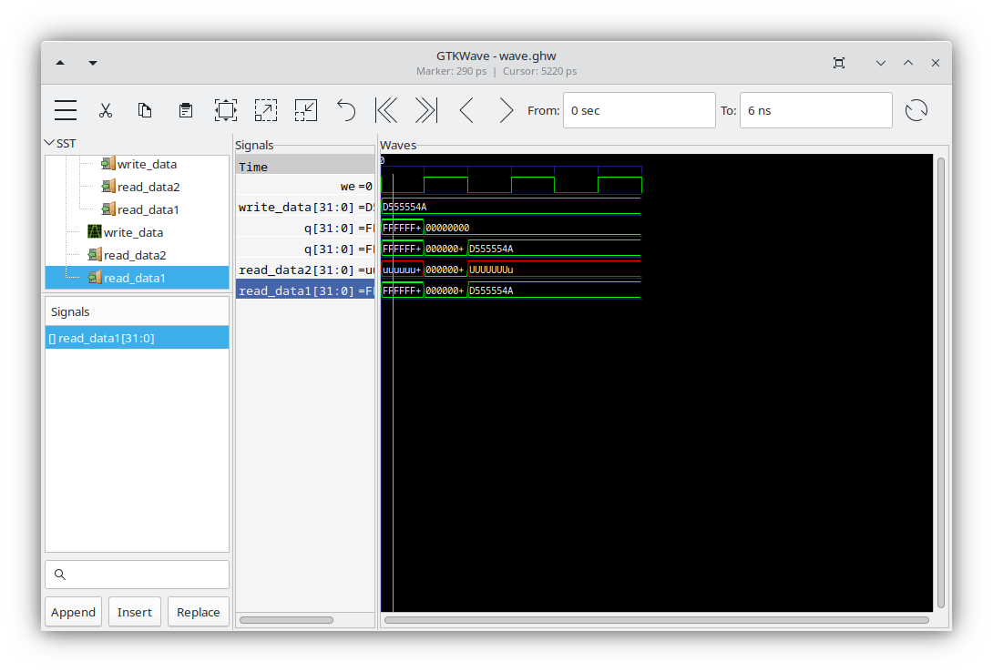
Nein, es scheint zu tun, die Testbench war falsch.
Also, es tut doch, sorry, ich war draussen, das Smartphone hatte Akku leer und ich keine Internetverbindung


Es tut, die Testbench war falsch.
Code: Alles auswählen
-- so ist sie richtig

architecture behaviour of regset2testbench is
    component regset2
    port (
        read_data1: out std_logic_vector (31 downto 0);
        read_data2: out std_logic_vector (31 downto 0);
        write_data: in std_logic_vector (31 downto 0);
        read_reg1: in std_logic;
        read_reg2: in std_logic;
        write_reg: in std_logic;
        we: in std_logic
    );
    end component;
    signal write_data: std_logic_vector (31 downto 0);
    signal read_reg1: std_logic;
    signal read_reg2: std_logic;
    signal write_reg: std_logic;
    signal we: std_logic;
begin
    rset1: regset2 PORT MAP (read_data1=>read_data1, read_data2=>read_data2, write_data=>write_data, read_reg1=>read_reg1, read_reg2=>read_reg2, write_reg=>write_reg, we=>we);

    we <= '0' after 0 ns, '1' after 1 ns, '0' after 2 ns, '1' after 3 ns, '0' after 4 ns, '1' after 5 ns, '0' after 6 ns, '1' after 7 ns, '0' after 8 ns, '1' after 9 ns, '0' after 10 ns;
    write_reg <= '1' after 0 ns;
    read_reg1 <= '1' after 0 ns, '0' after 5 ns;
    read_reg2 <= '0' after 0 ns, '1' after 5 ns;

    write_data (0) <= '0';
    write_data (1) <= '1';
    write_data (2) <= '0';
    write_data (3) <= '1';
    write_data (4) <= '0';
    write_data (31) <= '1';
    write_data (5) <= '0';
    write_data (6) <= '1';
    write_data (7) <= '0';
    write_data (8) <= '1';
    write_data (9) <= '0';
    write_data (10) <= '1';
    write_data (11) <= '0';
    write_data (12) <= '1';
    write_data (13) <= '0';
    write_data (14) <= '1';
    write_data (15) <= '0';
    write_data (16) <= '1';
    write_data (17) <= '0';
    write_data (18) <= '1';
    write_data (19) <= '0';
    write_data (20) <= '1';
    write_data (21) <= '0';
    write_data (22) <= '1';
    write_data (23) <= '0';
    write_data (24) <= '1';
    write_data (25) <= '0';
    write_data (26) <= '1';
    write_data (27) <= '0';
    write_data (28) <= '1';
    write_data (29) <= '0';
    write_data (30) <= '1';

end;
Code: Alles auswählen
-- Und hier das ganze - Bereits mit Kaskadierung

library ieee;
use ieee.std_logic_1164.all;

entity rslatch is
port (
    r, s: in std_logic;
    q: out std_logic
);
end;

architecture verhalten of rslatch is
    signal q1, q2: std_logic;
    signal init: std_logic;
begin
    init <= '0' after 0 ns, '1' after 1 ns;

    q1 <= '1' when (init='0') else
            (q2 nor r);
    q2 <= '0' when (init='0') else
            (q1 nor s);
    q <= q1;
end;

library ieee;
use ieee.std_logic_1164.all;

entity clockcontrolledrslatch is
port (
    r, s: in std_logic;
    c: in std_logic;
    q: out std_logic
);
end;

architecture behaviour of clockcontrolledrslatch is
    component rslatch
    port (
        r, s: in std_logic;
        q: out std_logic
    );
    end component;
    signal r1, s1: std_logic;
begin
    rslatch1: rslatch PORT MAP (r=>r1, s=>s1, q=>q);
    s1 <= (s and c);
    r1 <= (r and c);
end;

library ieee;
use ieee.std_logic_1164.all;

entity dlatch is
port (
    d: in std_logic;
    c: in std_logic;
    q: out std_logic
);
end;

architecture behaviour of dlatch is
    component clockcontrolledrslatch
    port (
        r, s: in std_logic;
        c: in std_logic;
        q: out std_logic
    );
    end component;
    signal r1, s1: std_logic;
begin
    clockcontrolledrslatch1: clockcontrolledrslatch PORT MAP (r=>r1, s=>s1, q=>q, c=>c);
    s1 <= not d;
    r1 <= d;
end;

library ieee;
use ieee.std_logic_1164.all;

entity dmsflipflop is
port (
    d: in std_logic;
    c: in std_logic;
    q: out std_logic
);
end;

architecture behaviour of dmsflipflop is
    component dlatch
    port (
        d: in std_logic;
        c: in std_logic;
        q: out std_logic
    );
    end component;
    signal d1, d2: std_logic;
    signal c1, c2: std_logic;
    signal q1, q2: std_logic;
begin
    dlatch1: dlatch PORT MAP (d=>d1, c=>c1, q=>q1);
    dlatch2: dlatch PORT MAP (d=>d2, c=>c2, q=>q2);
    c1 <= c;
    c2 <= not c;
    d1 <= d;
    d2 <= q1;
    q <= q2;
end;

library ieee;
use ieee.std_logic_1164.all;

entity flipfloptestbench is
port (
    q: out std_logic
);
end;

architecture behaviour of flipfloptestbench is
    component dmsflipflop
    port (
        d: in std_logic;
        c: in std_logic;
        q: out std_logic
    );
    end component;
    signal d, c: std_logic;
begin
    dmsflipflop1: dmsflipflop PORT MAP (q=>q, d=>d, c=>c);

    c <= '0' after 0 ns, '1' after 20 ns, '0' after 40 ns, '1' after 60 ns, '0' after 80 ns, '1' after 100 ns, '0' after 120 ns, '1' after 140 ns,
            '0' after 160 ns, '1' after 180 ns, '0' after 200 ns, '1' after 220 ns, '0' after 240 ns,
            '1' after 260 ns, '0' after 280 ns, '1' after 300 ns, '0' after 320 ns, '1' after 340 ns;
    d <= '0' after 0 ns, '1' after 150 ns, '0' after 250 ns;

end;

library ieee;
use ieee.std_logic_1164.all;

entity reg32 is
port (
    we: in std_logic;
    q: out std_logic_vector (31 downto 0);
    d: in std_logic_vector (31 downto 0)
);
end;

architecture behaviour of reg32 is
    component dmsflipflop
    port (
        d: in std_logic;
        c: in std_logic;
        q: out std_logic
    );
    end component;
begin
    l1:
    for i in 0 to 31 generate
        dmsflipflop1: dmsflipflop PORT MAP (q=>q(i), d=>d(i), c=>we);
    end generate;
end;

library ieee;
use ieee.std_logic_1164.all;

entity reg32testbench is
port (
    q: out std_logic_vector (31 downto 0)
);
end;

architecture behaviour of reg32testbench is
    component reg32
    port (
        d: in std_logic_vector (31 downto 0);
        we: in std_logic;
        q: out std_logic_vector (31 downto 0)
    );
    end component;
    signal d: std_logic_vector (31 downto 0);
    signal we: std_logic;
begin
    reg32a: reg32 PORT MAP (d=>d, q=>q, we=>we);

    d(0) <= '1';
    d(1) <= '0';
    d(2) <= '1';
    d(3) <= '0';
    d(4) <= '1';
    d(5) <= '0';
    d(6) <= '1';
    d(7) <= '0';
    d(8) <= '1';
    d(9) <= '1';
    d(10) <= '0';
    d(11) <= '1';
    d(12) <= '0';
    d(13) <= '1';
    d(14) <= '0';
    d(15) <= '1';
    d(16) <= '0';
    d(17) <= '1';
    d(18) <= '0';
    d(19) <= '1';
    d(20) <= '0';
    d(21) <= '1';
    d(22) <= '0';
    d(23) <= '1';
    d(24) <= '0';
    d(25) <= '1';
    d(26) <= '0';
    d(27) <= '1';
    d(28) <= '0';
    d(29) <= '1';
    d(30) <= '0';
    d(31) <= '1';
    we <= '0' after 0 ns, '1' after 10 ns, '0' after 20 ns, '1' after 30 ns, '0' after 40 ns,    '1' after 60 ns, '0' after 80 ns;

end;

library ieee;
use ieee.std_logic_1164.all;

entity mux32x2_1 is
port (
    b: in std_logic_vector (31 downto 0);
    a: in std_logic_vector (31 downto 0);
    c: out std_logic_vector (31 downto 0);
    s: in std_logic
);
end;

architecture behaviour of mux32x2_1 is
begin
    l1:
    for i in 0 to 31 generate
        c (i) <= (a (i) and s) or (b (i) and not s);
    end generate;
end;

library ieee;
use ieee.std_logic_1164.all;

entity mux32x2_1testbench is
port (
    c: out std_logic_vector (31 downto 0)
);
end;

architecture behaviour of mux32x2_1testbench is
    component mux32x2_1
    port (
        b: in std_logic_vector (31 downto 0);
        a: in std_logic_vector (31 downto 0);
        c: out std_logic_vector (31 downto 0);
        s: in std_logic
    );
    end component;
    signal a: std_logic_vector (31 downto 0);
    signal b: std_logic_vector (31 downto 0);
    signal s: std_logic;
begin
    m: mux32x2_1 PORT MAP (b=>b, a=>a, c=>c, s=>s);

    a (0) <= '0';
    a (1) <= '1';
    a (2) <= '0';
    a (3) <= '1';
    a (4) <= '0';
    a (5) <= '0';
    a (6) <= '1';
    a (7) <= '0';
    a (8) <= '1';
    a (9) <= '0';
    a (10) <= '1';
    a (11) <= '0';
    a (12) <= '1';
    a (13) <= '0';
    a (14) <= '1';
    a (15) <= '0';
    a (16) <= '1';
    a (17) <= '0';
    a (18) <= '1';
    a (19) <= '0';
    a (20) <= '1';
    a (21) <= '0';
    a (22) <= '1';
    a (23) <= '0';
    a (24) <= '1';
    a (25) <= '0';
    a (26) <= '1';
    a (27) <= '0';
    a (28) <= '1';
    a (29) <= '0';
    a (30) <= '1';
    a (31) <= '1';

    b (0) <= '0';
    b (1) <= '0';
    b (2) <= '0';
    b (3) <= '1';
    b (4) <= '0';
    b (5) <= '1';
    b (6) <= '0';
    b (7) <= '0';
    b (8) <= '1';
    b (9) <= '0';
    b (10) <= '1';
    b (11) <= '0';
    b (12) <= '0';
    b (13) <= '0';
    b (14) <= '1';
    b (15) <= '0';
    b (16) <= '0';
    b (17) <= '1';
    b (18) <= '1';
    b (19) <= '0';
    b (20) <= '1';
    b (21) <= '0';
    b (22) <= '0';
    b (23) <= '1';
    b (24) <= '1';
    b (25) <= '0';
    b (26) <= '1';
    b (27) <= '0';
    b (28) <= '1';
    b (29) <= '0';
    b (30) <= '1';
    b (31) <= '1';

    s <= '0' after 0 ns, '1' after 10 ns, '0' after 20 ns;

end;

library ieee;
use ieee.std_logic_1164.all;

entity regset2 is
port (
    read_data1: out std_logic_vector (31 downto 0);
    read_data2: out std_logic_vector (31 downto 0);
    write_data: in std_logic_vector (31 downto 0);
    read_reg1: in std_logic;
    read_reg2: in std_logic;
    write_reg: in std_logic;
    we: in std_logic
);
end;

architecture behaviour of regset2 is
    component reg32
    port (
        we: in std_logic;
        q: out std_logic_vector (31 downto 0);
        d: in std_logic_vector (31 downto 0)
    );
    end component;
    component mux32x2_1
    port (
        b: in std_logic_vector (31 downto 0);
        a: in std_logic_vector (31 downto 0);
        c: out std_logic_vector (31 downto 0);
        s: in std_logic
    );
    end component;
    signal we1, we2: std_logic;
    signal r_dat1: std_logic_vector (31 downto 0);
    signal r_dat2: std_logic_vector (31 downto 0);
begin
    reg1: reg32 PORT MAP (we=>we1, d=>write_data, q=>r_dat1);
    reg2: reg32 PORT MAP (we=>we2, d=>write_data, q=>r_dat2);
    m1: mux32x2_1 PORT MAP (a=>r_dat1, b=>r_dat2, c=>read_data1, s=>read_reg1);
    m2: mux32x2_1 PORT MAP (a=>r_dat1, b=>r_dat2, c=>read_data2, s=>read_reg2);

    we1 <= (write_reg and we);
    we2 <= (not write_reg and we);
end;

library ieee;
use ieee.std_logic_1164.all;

entity regset2testbench is
port (
    read_data1: out std_logic_vector (31 downto 0);
    read_data2: out std_logic_vector (31 downto 0)
);
end;

architecture behaviour of regset2testbench is
    component regset2
    port (
        read_data1: out std_logic_vector (31 downto 0);
        read_data2: out std_logic_vector (31 downto 0);
        write_data: in std_logic_vector (31 downto 0);
        read_reg1: in std_logic;
        read_reg2: in std_logic;
        write_reg: in std_logic;
        we: in std_logic
    );
    end component;
    signal write_data: std_logic_vector (31 downto 0);
    signal read_reg1: std_logic;
    signal read_reg2: std_logic;
    signal write_reg: std_logic;
    signal we: std_logic;
begin
    rset1: regset2 PORT MAP (read_data1=>read_data1, read_data2=>read_data2, write_data=>write_data, read_reg1=>read_reg1, read_reg2=>read_reg2, write_reg=>write_reg, we=>we);

    we <= '0' after 0 ns, '1' after 1 ns, '0' after 2 ns, '1' after 3 ns, '0' after 4 ns, '1' after 5 ns, '0' after 6 ns, '1' after 7 ns, '0' after 8 ns, '1' after 9 ns, '0' after 10 ns;
    write_reg <= '1' after 0 ns;
    read_reg1 <= '1' after 0 ns, '0' after 5 ns;
    read_reg2 <= '0' after 0 ns, '1' after 5 ns;

    write_data (0) <= '0';
    write_data (1) <= '1';
    write_data (2) <= '0';
    write_data (3) <= '1';
    write_data (4) <= '0';
    write_data (31) <= '1';
    write_data (5) <= '0';
    write_data (6) <= '1';
    write_data (7) <= '0';
    write_data (8) <= '1';
    write_data (9) <= '0';
    write_data (10) <= '1';
    write_data (11) <= '0';
    write_data (12) <= '1';
    write_data (13) <= '0';
    write_data (14) <= '1';
    write_data (15) <= '0';
    write_data (16) <= '1';
    write_data (17) <= '0';
    write_data (18) <= '1';
    write_data (19) <= '0';
    write_data (20) <= '1';
    write_data (21) <= '0';
    write_data (22) <= '1';
    write_data (23) <= '0';
    write_data (24) <= '1';
    write_data (25) <= '0';
    write_data (26) <= '1';
    write_data (27) <= '0';
    write_data (28) <= '1';
    write_data (29) <= '0';
    write_data (30) <= '1';

end;

library ieee;
use ieee.std_logic_1164.all;

entity regset4 is
port (
    read_data1: out std_logic_vector (31 downto 0);
    read_data2: out std_logic_vector (31 downto 0);
    write_data: in std_logic_vector (31 downto 0);
    read_reg1: in std_logic_vector (1 downto 0);
    read_reg2: in std_logic_vector (1 downto 0);
    write_reg: in std_logic_vector (1 downto 0);
    we: in std_logic
);
end;

architecture behaviour of regset4 is
    component regset2
    port (
        read_data1: out std_logic_vector (31 downto 0);
        read_data2: out std_logic_vector (31 downto 0);
        write_data: in std_logic_vector (31 downto 0);
        read_reg1: in std_logic;
        read_reg2: in std_logic;
        write_reg: in std_logic;
        we: in std_logic
    );
    end component;
    component mux32x2_1
    port (
        b: in std_logic_vector (31 downto 0);
        a: in std_logic_vector (31 downto 0);
        c: out std_logic_vector (31 downto 0);
        s: in std_logic
    );
    end component;
    signal r_reg1: std_logic;
    signal r_reg2: std_logic;
    signal wrt_dat1: std_logic_vector (31 downto 0);
    signal wrt_dat2: std_logic_vector (31 downto 0);
begin
    r2a: regset4 PORT MAP (read_data1=>read_data1, read_data2=>read_data2, write_data=>wrt_dat1, read_reg1=>read_reg1 (0), read_reg2=>read_reg2 (0), write_reg=>write_reg (0), we=>r_reg1);
    r2b: regset4 PORT MAP (read_data1=>read_data1, read_data2=>read_data2, write_data=>wrt_dat2, read_reg1=>read_reg1 (0), read_reg2=>read_reg2 (0), write_reg=>write_reg (0), we=>r_reg2);
    m1: mux32x2_1 PORT MAP (a=>wrt_dat1, b=>wrt_dat2, c=>write_data, s=>write_reg (1));
    r_reg1 <= read_reg1 (1) and we;
    r_reg2 <= not read_reg1 (1) and we;
end;

library ieee;
use ieee.std_logic_1164.all;

entity regset8 is
port (
    read_data1: out std_logic_vector (31 downto 0);
    read_data2: out std_logic_vector (31 downto 0);
    write_data: in std_logic_vector (31 downto 0);
    read_reg1: in std_logic_vector (2 downto 0);
    read_reg2: in std_logic_vector (2 downto 0);
    write_reg: in std_logic_vector (2 downto 0);
    we: in std_logic
);
end;

architecture behaviour of regset8 is
    component regset4
    port (
        read_data1: out std_logic_vector (31 downto 0);
        read_data2: out std_logic_vector (31 downto 0);
        write_data: in std_logic_vector (31 downto 0);
        read_reg1: in std_logic_vector (1 downto 0);
        read_reg2: in std_logic_vector (1 downto 0);
        write_reg: in std_logic_vector (1 downto 0);
        we: in std_logic
    );
    end component;
    component mux32x2_1
    port (
        b: in std_logic_vector (31 downto 0);
        a: in std_logic_vector (31 downto 0);
        c: out std_logic_vector (31 downto 0);
        s: in std_logic
    );
    end component;
    signal r_reg1: std_logic;
    signal r_reg2: std_logic;
    signal wrt_dat1: std_logic_vector (31 downto 0);
    signal wrt_dat2: std_logic_vector (31 downto 0);
begin

end;

library ieee;
use ieee.std_logic_1164.all;

entity regset16 is
port (
    read_data1: out std_logic_vector (31 downto 0);
    read_data2: out std_logic_vector (31 downto 0);
    write_data: in std_logic_vector (31 downto 0);
    read_reg1: in std_logic_vector (3 downto 0);
    read_reg2: in std_logic_vector (3 downto 0);
    write_reg: in std_logic_vector (3 downto 0);
    we: in std_logic
);
end;

library ieee;
use ieee.std_logic_1164.all;

entity regset32 is
port (
    read_data1: out std_logic_vector (31 downto 0);
    read_data2: out std_logic_vector (31 downto 0);
    write_data: in std_logic_vector (31 downto 0);
    read_reg1: in std_logic_vector (4 downto 0);
    read_reg2: in std_logic_vector (4 downto 0);
    write_reg: in std_logic_vector (4 downto 0);
    we: in std_logic
);
end;Für die Auswahl der Register, habe ich das untere Bit übergeben. Das obere verwende ich mit WE - muss ich noch testen